We’ve all seen production truss load tables before. At the very least, they provide allowable Centre Point Load (CPL) and Uniformly Distributed Load (UDL) for given spans. Typically, these are values calculated by a suitably qualified Engineer contracted by the truss manufacturer.
How to calculate truss loads and understanding the Load Table
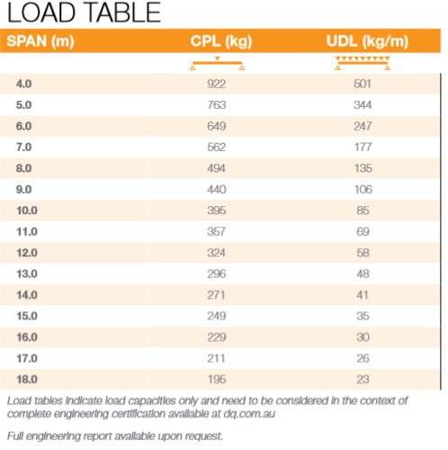
Fig 1 – Global Truss F34 Load Table
Reading across the load table for a given SPAN gives the maximum CPL (Centre Point Load) OR UDL (Uniform Distributed Load) for that span
EXAMPLE 1: SPAN 7m > CPL = 562kg
562kg is the maximum CPL weight suspended symmetrically at mid-span
EXAMPLE 2: SPAN 16m > UDL = 30kg/m
16 x 30kg = 480kg is the maximum UDL weight suspended symmetrically along the span
All other configurations, for example truss spans with 3 or more points, square or rectangular grids on 4 or more points, goal post structures, it is recommended that the user consult a suitably qualified engineer.
Now to look at the load table and its limitations.
The first thing that we must take into consideration when using this table is the position of the supports considered by suitably qualified engineer’s when calculating the allowable loads. A simple span is the typical configuration used by these engineers whereby truss is supported at the end nodes of the truss. This means that all the loads will be acting between the supports. Notably there is no cantilever effect beyond each support.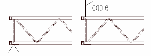
The load chart lists a range of spans with the corresponding allowable Centre Point Load (CPL) in kg and Uniformly Distributed Loads (UDL) in kg per metre.
Note that some charts list the UDL as TOTAL kg for a given span.
More detailed charts or the full engineering reports will list other load configurations such as Third Point Loads, Quarter Point Loads or Fifth Point Loads.

Fig 3 – Typical Load Scenarios for Load Charts
It should be noted that for each of these scenarios, the Point Load is the same, as is the spacing between each for a given span.
For instance, for a UDL, usually calculated at 0.5m centres, every point along the span is assumed to be the same weight. This is typical of some LED screens or a lighting truss with multiples of the exact same lighting fixture attached equidistant along the truss.
For a 4th point scenario, 3 loads of equal weight are attached equidistant along the span. i.e. the span is divided into 4 equal lengths
If you are planning to attach varying loads at adjacent points, or the spacing vaies, the Load Table does not apply.
Now consider multiple lifting points on the truss. As we have discussed in our Multi Point Rigging tech tip (https://dq.com.au/technical-tips-and-topics/multi-point-rigging-its-not-so-simple/), the calculation of support reactions of a truss with 3 or more pick up points is mathematically indeterminate. i.e. this is no longer in a “simple span” configuration and the Load Table does not apply.
Because of the wide variety of loads that are placed on trusses, and the almost endless ways that truss can be connected together, it is simply not viable to have a single load table for every eventuality.
Truss Structures
Most people would agree that something like a truss roof system is clearly into the realm of a structure, but which other common truss setups also need to be treated as a structure?
One common question is “What about a truss arch? Surely that’s a simple span. It has a straight span of truss supported at each end by the uprights. Can’t I use the load charts for that?”
Yes, the load chart can be used for the horizontal span in isolation.
No, the capacity of the truss arch as a rigging system requires input from a suitably qualified engineer
When truss is used vertically as a tower, the allowable internal normal/compression forces in the truss are governed by its capacity to resist buckling.

Fig 4 – Tower buckling under compression
The internal reactions become increasingly complex in a truss arch because of the rigid connection between the towers and the horizontal span inducing bending at the top of the tower
The engineering associated with buckling is beyond the scope of this tech tip.
Safe use of a truss arch requires input from a suitably qualified engineer.
Truss grids are another common truss structure used in the entertainment industry. Consider the square grid below and the theoretical reactions at the supports from a uniformly distributed load:

Fig 5 – Load distribution on a grid (UDL)
Using the same theory as a straight truss on 3 or more points, the reactions at the supports for this grid are mathematically indeterminate l. Each truss span making up the grid transfers the load in complex ways, and which means the manufacturer’s load chart developed only for simple spans cannot be used to determine the loading capacity of each truss. Sounding again like a broken record, take it to a suitably qualified engineer.
Of greater significance for this and similar scenarios, the reactions at the supports are theoretical and come with a recommendation to use a load monitoring system to avoid possible over-loading of the supporting structure.
Wind Loading
So far, we have considered only production loads attached to the truss; typically lights, LED screens, PA equipment, curtains, side walls, roof covers and banners.
When using equipment outdoors, environmental loads must be applied to the truss structure. It should also be noted that even in some indoor locations you may need to account for some amount of wind loading. Large arenas or convention centres with doors or loading docks that open to the outside can funnel wind into the interior and cause wind loads on truss. Even a simple truss arch with a curtain can become a very large sail.
All these environmental loads must be considered by an Engineer, and they will be able to provide you with ballast and guy wire requirements to ensure that the loads applied to the structure are safely within the capacity of the truss and that it remains stable. The engineer can also provide you with a wind action plan which will outline at what wind speed it is safe to raise or lower a roof, at what speed you need to remove side panels and, ultimately, at what speed you need to evacuate the site.
So, if environmental loads are going come into play, you will need a structural engineering report. It’s that simple. There are varying requirements from state-to-state so there may be special forms in addition to the report required for your locality. Confirm the requirements with your engineer and local authorities. It is also worth noting that when you engage a structural engineer, they must be registered to practice in your state.
From our experience we recommend engineers who are experienced in entertainment rigging as it helps if they are to speed with the products we use and the practicalities of their use in temporary structures. Of course, Design Quintessence can work with any engineer to provide product certification along with full standard product engineering reports and detailed 3D CAD drawings for the analysis.
Summary
The use of production truss as a span suspended on 3 or more points or used within a grid or other structure requires structural analysis to determine the internal forces resulting from the applied loads.
Essentially, this is beyond the scope of the Load Table obtained from the Truss Manufacturer
If a structure you are responsible for is not covered by a Load Chart or Structural Report, you must engage a suitably qualified engineer to advise you on the structural integrity, practicality, and safety of the structure.
In conclusion, when do we need an engineer to sign off?
Whenever the truss is used in a configuration that is not covered by an existing load chart or engineer’s report. Typically these are going to be for simple spans supported at 2 points. If your truss has more than 2 points, or it’s connected to other truss as part of a structure, you need to get the advice of a suitably qualified engineer.