Can you put loads on top of a truss?
Typically, in entertainment use, loads on trusses are attached along the lower chords with the load centred below the truss. For example, lights, speakers and LED screens are generally attached below the truss.
The truss is being used as intended by the design engineer – provided we stay within the loading limits. But what if we want to put something on top of the truss? Can we do that safely? Let’s take a look at how truss works and try to figure out what we can and can’t do.
How Truss Reacts To Loads
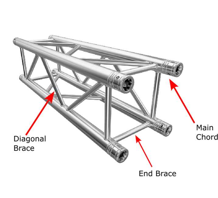
A lattice truss we see some standard features.
- Main Chords of larger diameter tubes are connected to each other by smaller diameter Diagonal Braces.
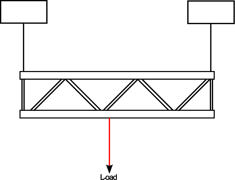
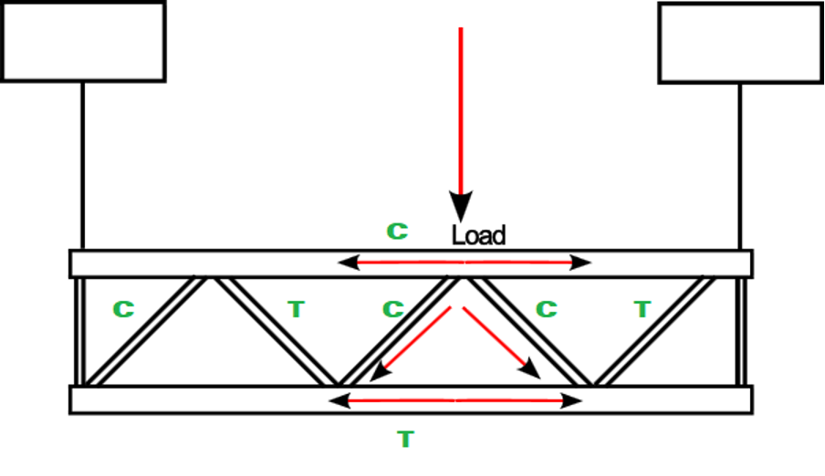
In a simple scenario loads on the bottom chord of the truss it might look like this.
In this scenario we are considering a single load at roughly centre span of the truss suspended between two hoists. We now look at how that load is going to transfer through the truss.
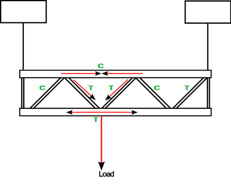
The forces transfer through the truss along the main chord(s) and the braces to the hoists. This scenario puts the bottom chord in tension, the braces in alternating tension/compression and the upper chord in compression.
The truss is in equilibrium and remains stable.
If we next consider the load to the top chord we see the following.
In this diagram we see that the loads transfer in a similar fashion.
When engineers calculate the loading capacity of truss, they consider the maximum allowable forces in the chords and braces both in tension and compression. Because of this we know that we can apply the loads above or below the truss provided we stay within the limits specified by the engineer.
However, top loading must also consider the stability of the truss.
Centre of Gravity and Rotation
Consider a box truss suspended with a typical basket sling arrangement. The connection point of the sling is a point of rotation.
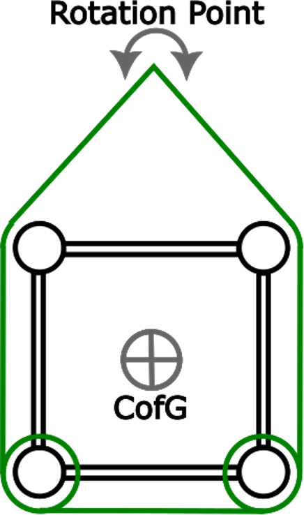
With no load on the truss, the centre of gravity [CofG] of the truss is centred and is below the Rotation Point.
This truss is stable and unlikely to roll in the basket, even without the wraps indicated.
There are no external forces to cause instability.
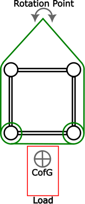
Load attached below the truss causes the CofG to move down and further away from the rotation point.
This increases the stability of the truss.

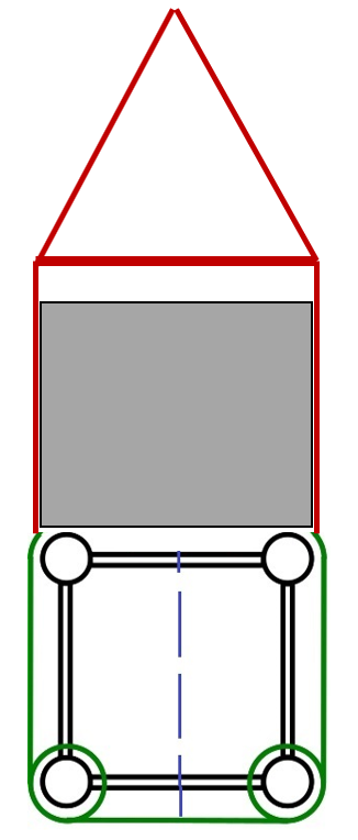
Load attached to the top of the truss.
The CofG of the system moves up with its actual position determined by the relative weight of the truss and applied load(s).
To prevent instability the load is centred when attached above the truss.
With the CofG above the truss and not centred the potential for the truss to roll or tip is increased.
This rolling or tipping can be mitigated by wrapping the slings as indicated and using a deeper basket if drift height permits. But this sling alone should not be depended on.
Loads attached top and bottom should always be assessed.
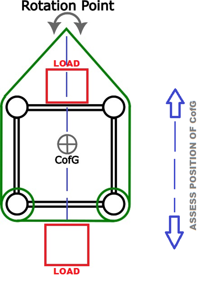
The position of the CofG will depend on the relative weight of loads attached above and below the truss.
Load attached to the Top of the truss at Rigging PointsThe position of the load can help ensure the truss is stable
Summary
- When rigging truss and attaching loads the stability of the truss must be considered.
- The truss must be stabilised with loads centred for the engineer’s load limits to be applied
We can say that top loading and combined top and bottom loading is allowable on entertainment trussing but is conditional on the following.
- The total applied load is within the engineer’s load limits
- Loads are attached/secured to the truss
- The CofG is centred / the system is balanced and level – along and across
- The position of the CofG is determined based on
- Self-weight of truss
- Applied loads
Where complex loading/rigging scenarios are involved, it is recommended that qualified engineers with relevant experience and knowledge are consulted for the appropriate structural and stability calculations.
DISCLAIMER: The information provided in this document is offered as a best practice guideline for consideration by experienced and competent personnel. No liability will be accepted for misuse or misinterpretation.

